
Call Us Now:
0345 193 0615
 |
This tutorial covers the fitting of three part BNC crimp connectors to RG59 coaxial cable, but it is also appropriate to many other types of coaxial cable and RF connector – things like the strip depth may change but the principles are the same. |
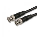
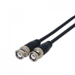
It is good to be prepared to make or repair your own BNC and RF cables. Whilst it is undoubtedly cheaper and possibly better to purchase ready made BNC cables from Leads Direct there may be many instances where you may need a cable or cable repair instantly, and making a lead will get you out of a jam. However making several cables can be very labour intensive and therefore expensive – just the wages to make the cable will normally be far more than the cost of a ready made lead. Factory made leads and cables typically have better tolerances, and consequently provide better signal quality than home made cables.
In order to make a cable using BNC connectors you will need some tools. These can be purchased in a kit, or individually, and a range can be viewed on the tools section secure online shopping area. For the purposes of this tutorial you will need the following Tools:
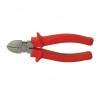 |
A set of cutters to trim the cable to length |
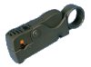 |
A good coaxial cable stripper is a very useful tool and will ensure that the cable is accurately stripped reducing the risk of both short and open circuit connections |
 |
A good quality crimp tool capable of handling a wide range of different sizes of crimp – the centre pin and the sleeve are hugely different in size. |
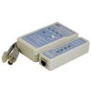 |
A network cable tester with BNC fittings |
 |
If you don’t have a cable tester, a standard test meter can be used instead. |
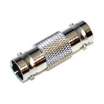
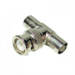
This tutorial describes using a three part BNC connector. Developed in the late 1940s as a miniature version of the Type C connector, BNC stands for Bayonet Neill Concelman and is named after Amphenol engineer Carl Concelman. The BNC product line is a miniature quick connect/disconnect RF connector. It features two bayonet lugs on the female connector; mating is achieved with only a quarter turn of the coupling nut. BNCs are ideally suited for cable termination for miniature to subminiature coaxial cable (RG-58, 59, to RG-179, RG-316, etc.)

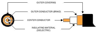
Coax cable is usually circular when viewed end on. It has a center conductor surrounded by dielectric insulating material, which in turn is covered by a braid to shield against electromagnetic interference (EMI). The outer covering is the “jacket”.
The nonconductive or dielectric material separates the two conductors. The inner core carries the main signal whilst the outer conductor (braid) acts as a shield and helps isolate the center conductor from spurious electromagnetic interference. The outer covering helps to physically protect the conductors.
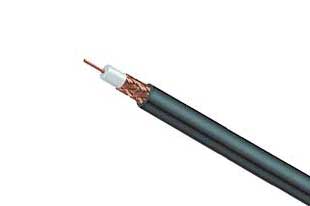
The most common coaxial cable used with BNC connectors is RG59/U, a 75 ohm cable. Not only is coax the most commonly used cable, but also typically the least expensive, most reliable, most convenient, and easily maintained way of transferring electronic images in a video environment.
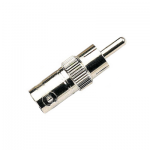
The first step is to cut the cable to the required length. Consider using a cable tie or wire tie wrap to coil the cable leaving sufficient loose cable at each end to facilitate making the connection. Make sure that you have the connector components ready to be used – the plug body, the centre pin, and the sleeve should be laid out where you can reach them easily.
You may want to use a small plastic organiser box, tupperware container or even an empty ice cream tub to hold the parts so that they don’t get dropped or lost – the centre pin in particular is very easy to lose and the plug is useless without it.
Take the sleeve and slide it over the cable BEFORE you start to strip it. Now you need to strip the cable using the following strip dimensions:
All cuts must be sharp and square. Make certain that you do not nick the braid, the dielectric insulation, or the
centre conductor. The easiest way to do this is to use a multi-cut coaxial cable stripper preset to the correct distances and depths. You can order one from our e-shop.
Next slide the centre pin onto the centre core, making sure that it butts up against the insulation. Leaving a gap can lead to short circuits, so this is a vital step. Now, use the crimp tool to permanently fix the centre pin in place.
Note that in the diagram above the braid has been opened out slightly but not peeled back. This is the preferred method as it allows the braid to remain entwined whilst still allowing the stem of the plug body to slide underneath ready to be crimped into place.
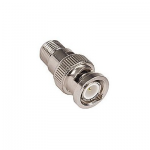
Once you have the braid ready, slide the centre pin into the plug body ensuring that the braid slides down the outside of the stem. When you have pushed it far enough into the body there should be a definite click as the pin locks into place. Make sure that the braid does not flair out at the plug body or it may extend below the sleeve at crimp time looking unsightly and potentially leading to reliability issues. Slide the sleeve over the braid and the plug stem until it touches the plug body, and then use the crimp tool to affix the sleeve to the cable and the plug.
Note that the crimp tool has two definite areas within the jaw – there will be an angled section and a rounded our empty outer section. The outer section causes the crimped sleeve to have two definite areas – the crimped area which supports the connection and holds the cable in place, and the uncrimped area which acts as a cable strain relief.
In order to ensure that these areas are correctly located, when actually crimping the rounded or empty section of the jaw must face away from the plug, and the plug must physically touch the jaw of the crimp tool. Squeeze until the jaws release and the process is complete. Repeat the process for the other end of the cable.
Having made the cable, it is very important to check that you have not made any mistakes – particularly electrical ones since a short circuit can damage connected equipment and an open circuit will mean that the cable will never work.
If you have a suitable network cable tester (such as our part MNT, available from our e-shop) you can simply connect both ends of the cable to the tester and read off the connections – Pin 1 should connect to pin 1 and pin 2 should connect to pin 2. If either does not connect you have an open circuit connection, and if both lights illuminate at the same time you have a short circuit.
If you do not have such a tester, you can use a normal test meter (such as our part MT600, available from our e-shop) to do the testing. If the meter has a beep setting, you can use that for an audible test. Otherwise, set it to read ohms and touch the two test prods together so that you can see what reading you should expect.
First, test for short circuit: on one of the plugs touch one test prod to the centre pin and one to the plug body. If there is a beep (or the meter reading changes if you are set to ohms) then you have a short circuit and the cable must be remade. You only need to test one end of the cable, since a short circuit will be apparent from either end.
Second test for open circuit: first touch one test prod to the centre pin at one end of the cable and touch the other prod to the centre pin at the other end. If you get a beep (or the reading changes if you are using ohms) then you do have a connection so the connection should be OK. Repeat the process for the body of the plugs, and you should get the same result. If either of these tests fail the cable will need to be remade.
Leads Direct makes great efforts to provide accurate and complete information. However, portions of the information contained in this website and any documents viewed on it or downloaded from it may be incorrect or not current. Any errors or omissions should be reported for investigation and correction. The information provided in any documents whether on our website or otherwise is provided "as is." No warranty of any kind, implied, expressed, or statutory, including but not limited to the warranties of non-infringement of third party rights, title, merchantability, fitness for a particular purpose, and freedom from computer virus, is given.