Call Us Now:
0345 193 0615
Leads Direct sells a huge range of ready made SCART Leads, SCART Accessories and associated products in various configurations which you can view and purchase by visiting our secure online shop which has literally thousands of products each with two sizes of image.
SCART stands for Syndicat francais des Constructeurs d’Appareils Radio et Television, and refers to the industry standard interface for physical and electrical interconnection between two pieces of audio-visual equipment, originated by the French company Peritel.
A SCART connector is used to connect two electronic devices such as a television set and a video cassette recorder (VCR) or DVD player. Each device has a female 21-pin connector interface. A cable with a male plug at each end is used to connect the devices. (The 21st pin is actually not a pin but a ground shield contact.)
Stereo audio, composite video, and control signals are provided in both directions. RGB video signals are input only. Most new television sets and VCRs in the European market and other countries that use the PAL video standard come equipped with one or more SCART connectors.
Different cables can be made using SCART connectors to serve different purposes. For example, a cable for connecting a VCR or a TV set to a high-fidelity audio system needs to use only three of the 21 pins. An enormous range of SCART leads are available from our secure online shop
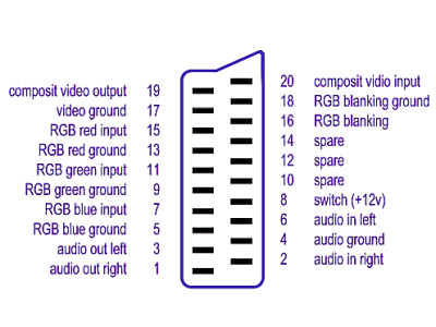
The connection standard requires that the pins are utilised in the following manner:
|
PIN
|
USE
|
LEVEL / IMPEDANCE
|
|
1
|
Audio Output (R)
|
0.5V / 1K-ohm
|
|
2
|
Audio Input (R)
|
0.5V / 10K-ohm
|
|
3
|
Audio Output (L)
|
0.5V / 1K-ohm
|
|
4
|
Audio Ground
|
——————–
|
|
5
|
Blue Ground
|
——————–
|
|
6
|
Audio Input (L)
|
0.5V / 10K-ohm
|
|
7
|
Blue
|
0.7Vp-p / 75ohm
|
|
8
|
Status (CVBS)
|
L:0-2V H:10 – 12V / 10K-ohm
|
|
9
|
Green Ground
|
——————–
|
|
10
|
Data D2B (Inverted)
|
——————–
|
|
11
|
Green
|
0.7Vp-p / 75 ohm
|
|
12
|
Data D2B
|
——————–
|
|
13
|
Red Ground
|
——————–
|
|
14
|
D2B Ground
|
——————–
|
|
15
|
Red
|
0.7Vp-p / 75 ohm
|
|
16
|
RGB Status/Fast Blanking
|
L:0-0.4V H:1-3V / 75 ohm
|
|
17
|
CVBS Video Ground
|
——————–
|
|
18
|
RGB Status Ground
|
——————–
|
|
19
|
Composite Video Output
|
1V / 75 ohm
|
|
20
|
Composite Video Input
|
1V / 75 ohm
|
|
21
|
Case Shield
|
———————
|
A 21 pin SCART cable with all pins connected is wired as per the following diagram:

We are often advised that auto AV selection is annoying, and asked how to prevent it occurring. The answer is to simply snip the wires connected to pin 8 of both Scart plugs! Once this has been done, the AV channel can only be invoked manually. However, before you even think about modifying your cable in this way, ensure that your TV allows you to manually select the AV input. Some apparently do not.
S-Video Cable for Scart S-Video Input |
|
|
S-Video Out
|
TV Scart (Input)
|
| Luminance Out (Y) | 20 Luminance In |
| Chrominance Out (C) | 15 Chrominance In |
| GND | 4+17 GND |
If you are seeking information on SCART wiring but cannot find it here, please email info@leadsdirect.co.uk and we will try to both answer your question and make sure that the information is made available through these pages for future reference.
Leads Direct makes great efforts to provide accurate and complete information. However, portions of the information contained in this website and any documents viewed on it or downloaded from it may be incorrect or not current. Any errors or omissions should be reported for investigation and correction. The information provided in any documents whether on our website or otherwise is provided "as is." No warranty of any kind, implied, expressed, or statutory, including but not limited to the warranties of non-infringement of third party rights, title, merchantability, fitness for a particular purpose, and freedom from computer virus, is given.