
Call Us Now:
0345 193 0615
Leads Direct sells a wide range of Telecoms cables ready made, including, RJ10, RJ11, RJ12, ADSL cables, and BT 4 and 6 wire cables and extensions. We can also make custom telecoms cables to your specification on request. However, there may well be times when you need help to find wiring information, to make your own leads or to repair an existing installation, and that is the purpose of this page.
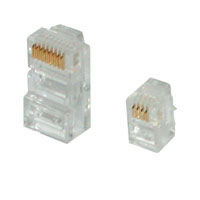
The connectors used for Telecoms wiring are usually referred to as ‘modular connectors, and also (technically incorrectly) by RJ reference – the RJ stands for Registered Jack and describes the way that the socket should be connected rather than the actual connector that is used. However, in the same way that people have come to call vacuum cleaners ‘Hoovers’ and ball point pens ‘Biros’ . There are a number of different ones available, the most common being shown below:
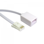
In the UK the most common way of connecting a telecommunications device to the telephone line is a BT plug. This is pretty much unique to the UK and comes in two types:
The 4 way plug is the standard one used on home and small business telephones. The 6 way plug is commonly used on telephone systems and the extra pins are used to transmit control signals which vary from manufacturer to manufacturer.
All of these connectors are fitted using a crimp tool, or more commonly several crimp tools since it is rare if not impossible to find a tool that will fit all of them. You will find a huge range of these and other cable related tools here.
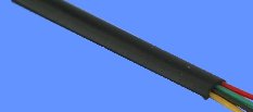
All the connectors listed above are usually fitted to flat profile telecoms cable with 4, 6, or 8 cores. The most common colour is white, but black and grey are fairly freely available as is cream in certain ready made lengths. Other colours are available but there may be a long lead time and a high minimum order quantity.
A great deal of confusion arises over the wiring of telecoms cables. Many people simply do not realise that the cores of the cables can be arranged in more than one order, and therefore experience problems when they try to connect a cable that originally came from a telephone to a modem, for example.
Confusion also abounds where the term ‘direct wired’ is used… some manufacturers of telecoms cables usually use this nomenclature to describe the situation where the cable is wired so that if you pull the cable out to its full length without any kinks or twists the plugs would be facing in the same direction, which in terms of pin connections would be a 100% reversal e.g. 1-6, 2-5, 3-4 etc. Others (notably APC) use it to describe a ‘straight through’ connection e.g. 1-1, 2-2, 3-3 etc.
The majority of manufacturers and distributors use the terms ‘direct wired’ to mean a full reversal and ‘straight through’ to mean a straight pin to pin assignment, but it is not safe to rely on this and you are advised to actively check the pin configuration before placing an order or starting to make or repair your own cables.
The most common wirings are as follows:
This listing is by no means exhaustive, and one of the most common problems reported to Leads Direct is not being able to get a cable configured correctly for the equipment. Luckily, Leads Direct offer a service whereby you can send in your original cable and have it tested and the wiring identified free of charge. If it is a standard format the correct cable can be supplied. If not, a custom lead can be made to almost any length required.
Confusion abounds in relation to pin numbers on the connectors, too. There is a lot of conflicting information on the internet, particularly where the BT plug is concerned. This arises because for some reason the BSI and BT managed to reverse the pin numbers between the plug and the socket, so effectively pin 6 on the plug actually connects to pin 1 in the socket and so on. As a result some people have taken the socket pin numbers and incorrectly applied them to the plug pins when creating wiring lists and diagrams. Even the far east manufacturers have made this error on their technical drawings, and as a result show the wrong pinout for the correct wiring in many cases.
RJ11 / 12 to BT Cables
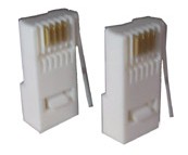
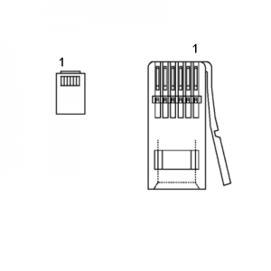
Even if they understand that the internal wiring can differ wildly on telephone cables, many people have trouble with determining what pinout they actually need to make the thing work. To work out the pinout for yourself, please use the pin numbers as shown in the diagram on the left.
Basically, if you hold the two connectors with the gold connectors facing towards you, with the RJ11 or RJ12 on the left and the BT431A or BT631A on the right, with modular connector clip facing away from you and the BT clip facing to the right, the pin numbers work inwards from the outside.
If your lead uses an RJ11 or BT431A then there are only four contacts but the six positions still remain – they are just unpopulated. Therefore you have to start counting those at pin 2 since pins 1 and 6 are not present.
If your lead uses an RJ12 or BT631A then you start counting at pin 1 as shown. Obviously if you have combination lead with four contacts on one end and six on the other then you will need to adjust accordingly, counting one end from pin one and the other from pin 2.
 RJ11 / 12 to RJ11 / 12
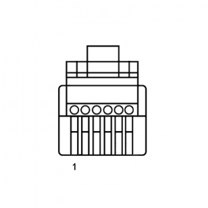
The RJ12 is a 6 position 6 contact modular connector commonly used in the UK with modems, telephones, and some lighting and data transfer applications.
In the US, the RJ11 is used at both ends of a telephone connection, just as it is here for a modem or ADSL router connection.
The connections are normally straight through, i.e. 1-1, 2-2, 3-3, 4-4, 5-5 and 6-6 on the RJ12 connector. For the RJ11 connector the connections are usually the same but without pins 1 and 6 which are not present.
In some cases, though, some very complicated crossovers are required particularly when connecting foreign devices to UK telecommunications systems. For one particular product, a video phone device, we make a special RJ11 double crossover cable – our part 2XXRJ11 – which is connected 2-3, 3-2, 4-5, 5-4, and of course we can always make custom leads and cables to any specification and in any quantity.
RJ10 (Also known as RJ9 and RJ22)
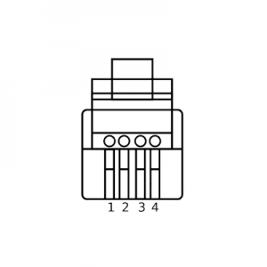
The RJ10 connector is a 4P4C (4 position 4 contact) connector that is commonly used for the curly handset cables on telephone handsets. It is also used for lighting control, low voltage control and some data transfer applications.
It is also sometimes used in tandem with RJ11 and RJ45 in conversion applications.
Looking at the pins, they are in the same location as in the RJ11 /12 to BT pinout above. The diagram on the left shows the pin numbers on the connector when looking at it end-on. The numbering goes from 1 to 4 as there are only four contacts and only four positions in which a contact can be placed. These are normally connected straight through, i.e. 1-1, 2-2, 3-3, 4-4
If you are seeking further information on Telecoms wiring but cannot find it here, please email info@leadsdirect.co.uk and we will try to both answer your question and make sure that the information is made available through these pages for future reference.
Leads Direct makes great efforts to provide accurate and complete information. However, portions of the information contained in this website and any documents viewed on it or downloaded from it may be incorrect or not current. Any errors or omissions should be reported for investigation and correction. The information provided in any documents whether on our website or otherwise is provided "as is." No warranty of any kind, implied, expressed, or statutory, including but not limited to the warranties of non-infringement of third party rights, title, merchantability, fitness for a particular purpose, and freedom from computer virus, is given.