
Call Us Now:
0345 193 0615
However, there may well be times when you need to make your own or repair an existing installation, and that is the purpose of this page. There is a standard to which Network Leads and Cables must be made, and the use of a common colour code prevents problems when moving to different sites or fixing different cables – if everyone uses the same colours there is no possibility of a mistake!
Network cables use modular crimp connectors which are fitted using a special crimp tool, which of course can be purchased from the Tools section. You will normally see the modular connectors listed as ‘RJ45’ connectors. Purists will object strongly to this designation, much as they do when S-Video cables are referred to as ‘S-VHS’, because it is technically incorrect. In general though as long as we all understand what is meant, I think we can accept that ‘a rose by any other name would smell as sweet’, as Shakespeare wrote…
From our research we understand that ‘RJ’ was an American national standard that was created so that a customer with a piece of FCC registered equipment could contact any local telephone company, anywhere in the US, give them the RJ requirement (Registered Jack) indicated on the device and the installer would know exactly how the jack needed to be wired. It had absolutely nothing to do with the size, brand or model of the connector itself; it was how the pins were wired when connecting to the public network (PSTN).
 Nowadays the term ‘RJ45’ is used generically to describe the crimp connector that is used for network wiring. In addition there are other modular connectors which also abuse the ‘RJ’ designation and are used in Telecoms Wiring – RJ9, RJ10, RJ11, RJ12, RJ22 etc.
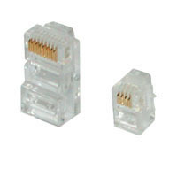
To the left you will see an image of two standard modular connectors, in this case on the left the one commonly known as RJ45 which has eight positions and eight contacts (8P8C), and on the right the one commonly known as RJ9, RJ10 or RJ22 which has four positions and four contacts (4P4C).
For the avoidance of doubt, we will refer to all connectors in these pages by the correct designation but will include the generic names in brackets beside the designation. In this case, as we are discussing Network connections, the connectors are 8P8C (RJ45) crimp connectors.
 Wiring pinouts refer to pin numbers on the connector in order to ensure that the correct connections are made. However, this is no use at all if you don’t know which pins are which!Looking at the top view or ‘contact side’ of the connector (with the gold metal contacts upwards and directly in front of you, the locking clip underneath) pin 1 is on the left. Subsequent contacts are numbered sequentially from left to right up to pin 8.
Looking at the front view, again with the clip downwards, pin 1 is on the right and again the pin numbers run sequentially up to pin 8 except this time from right to left.
The pin connections are listed below. The diagrams A and B below show the plug with the clip on the under side with the wires entering from the bottom of the connector.
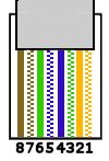
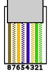
For standard Cat 5e network wiring, cables should be wired as per Fig 1 (EIA/TIA 568B) and the same at both ends. For Crossover network wiring fit the connectors as per Fig 1 at one end and Fig 2 at the other.
Cat 6 cabling is normally wired using the same colour code as Cat 5e, although the cable is of a higher specification to allow for higher data transmission speeds.
|
|
||||||||||||||||||||
|
Fig 1
|
|||||||||||||||||||||
 |
|
||||||||||||||||||||
|
Fig 2
|
|||||||||||||||||||||
For a full step by step tutorial on making modular connections, see our modular connection tutorial page. Otherwise, if you are ready to go it alone, here are some general tips that will help you to get it right…
The following table defines the properties of each defined cable type (as of July 2004)
|
EIA/TIA Category
|
Speed
|
LAN
|
100M Support
|
ISO Spec
|
EIA/TIA Spec
|
| Category 3 | 16Mhz | 10Mbit/s | 100Base-T4 | ||
| Category 4 | 20Mhz | 16Mbit/s | 100Base-T4 | ||
| Category 5 (5e) | 100Mhz | 100Mbit/s | 100Base-TX | ISO/IEC-11801 | TIA/EIA-568-A-5 |
| Category 6 | 250Mhz | 100Mbit/s | 100Base-TX | ISO/IEC-11801 | TIA/EIA-568-B.2-1 |
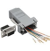
A range of RJ45 socket to Serial adaptors are available from our e-shop in the Computer Adaptors section, with both DB9 and DB25 male and female connections. These do not necessarily have a standard colour scheme but the most common are as follows:
RJ45 to DB9 Male
|
RJ45 Pin No:
|
Colour
|
| 1 | Blue |
| 2 | Orange |
| 3 | Black |
| 4 | Red |
| 5 | Green |
| 6 | Yellow |
| 7 | Brown |
| 8 | White |
RJ45 to DB9 Female
|
RJ45 Pin No:
|
Colour
|
| 1 | Red |
| 2 | Yellow |
| 3 | White |
| 4 | Green |
| 5 | Blue |
| 6 | Black |
| 7 | Orange |
| 8 | Brown |
If you are seeking information on Network wiring but cannot find it here, please email info@leadsdirect.co.ukand we will try to both answer your question and make sure that the information is made available through these pages for future reference
Leads Direct makes great efforts to provide accurate and complete information. However, portions of the information contained in this website and any documents viewed on it or downloaded from it may be incorrect or not current. Any errors or omissions should be reported for investigation and correction. The information provided in any documents whether on our website or otherwise is provided "as is." No warranty of any kind, implied, expressed, or statutory, including but not limited to the warranties of non-infringement of third party rights, title, merchantability, fitness for a particular purpose, and freedom from computer virus, is given.
£2.25
£2.70 inc VAT 1.5FLSOHUTPBLAdd to cart