
Call Us Now:
0345 193 0615
 |
This tutorial covers the fitting of modular connectors, and is appropriate to all types of modular connector including those generically (but incorrectly) known as RJ45, RJ11, RJ12, etc. |
It is good to be prepared to make or repair your own modular cables. Whilst it is undoubtedly cheaper and possibly better to purchase ready made Network Leads and Telecoms Leads from Leads Direct there may be many instances where you may need a cable or cable repair instantly, and making a lead will get you out of a jam. However making several cables can be very labour intensive and therefore expensive – the wages to make the cable will normally be far more than the cost of a ready made lead. Factory made leads and cables typically have better tolerances, and consequently provide better signal quality than home made cables.
This tutorial will cover in detail the process for making a Network cable using 8P8C (RJ45) modular connectors. However, the basic principles are the same regardless of the type of connector and cable being used and so you should be able to make telecoms cables using 6P4C (RJ11) and 6P6C (RJ12) and even 4P4C and BT white connectors by following the same instructions apart from the length of the stripped ends required. A table of strip lengths for the various types of cable and connector is provided towards the end of this tutorial, and details of BT wiring are available on our BT Wiring page.
In order to make a cable using modular connectors you will need some tools. These can be purchased in a kit, or individually, and a range can be viewed on our Tools page or the Tools section of our secure online shopping area. For the purposes of this tutorial you will need the following Tools:
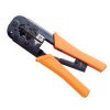 |
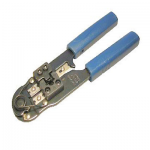
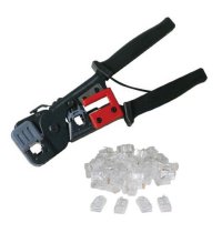
Crimp Tool: Whilst this is the most expensive part of making your own cables, it’s only a one-time start up cost. They can cost anywhere from £10 to £50 depending on the quality and features. Keep in mind that a good crimp tool will pay for itself after you make or repair a few cables, and that a low quality tool may not actually get the job done well, or indeed at all!. A good crimping tool has a pair of wire cutters built in, as well as a blade to strip insulation. It also might support crimping of other connectors such as 6P4C (RJ-11) and 6P6C (RJ12). The tool shown here is a professional model that costs £22.49 inc VAT and has all the features mentioned above. You can view it along with other models on our Tools page or in the Tools section of our secure online shopping area where you can order securely online if you wish. |
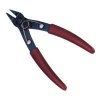 |
Side Cutters: You’ll need a pair of these to cut the wires in case the crimper doesn’t come with a built-in wire cutter. It may be worth purchasing large and small sizes, large to cut the cable and small to cut the individual cores. The ones shown here are a 125cm set that cost just £3.00 inc VAT and are ideal for trimming the ends of the cables. You can view them along with other models on our Tools page or in the Tools section of our secure online shopping area where you can order securely online if you wish. |
 |
Hobby or Utility knife: can be used to strip the insulation if your crimp tool does not have such a function built in. Some people prefer to use a knife as it seems to give more control over what they are doing and reduces the chances of nicking the internal wires. |
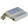 |
Network Cable Tester: Not absolutely essential, but will certainly help in finding out if you have done the job properly. A major advantage is when doing o nsite repairs, since you can use the unit to test cables that are actually routed inside trunking, walls, floors or ceilings and are not readily accessible. The model shown here costs £19.99 inc VAT and can be viewed along with other models on our Tools page or in the Tools section of our secure online shopping area where you can order securely online if you wish. |
 |
Multimeter: If you cannot afford a Network Cable tester, you can use a normal test meter to check for continuity faults. The model shown here is one that is actually used daily in our workshops here at Leads Direct! It costs £7.99 inc VAT and can be viewed along with other models on our Tools page or in the Tools section of our secure online shopping area where you can order securely online if you wish. |
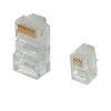 |
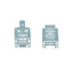
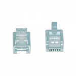
Connectors: The appropriate connectors for the type of cable you wish to make or repair. You may also wish to obtain strain relief covers or ‘Boots’ as they are known, if available for your chosen connector type. 8P8C (RJ-45) plugs are normally made for either solid conductors or stranded conductors. It is very important to be sure that the plug that you use matches the conductor type. It is extremely difficult to tell the difference between the two by looking at them. When you buy these plugs, be sure to sort and store them carefully as using the wrong type can cause intermittent problems. The 8P8C (RJ-45) connectors that we sell are rated for both Solid and Stranded cable. |
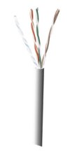 |
Cable: The correct cable for the job. For this tutorial that means Cat 5e cable – you can buy a 1000 feet (305m) roll of solid Cat 5 cable for as little as 13p or so per metre, and the flex is slightly more expensive depending on the type and quality. If you are buying from somewhere other than Leads Direct, don’t skimp on the cable, get the decent quality stuff. Check to make sure that the colour-coding on the wires is easily recognisable, and make sure that you select the correct type of cable for your application – there is a difference between solid (also known as ‘structural’ because it is often built into the structure of buildings) and stranded wire cable.Stranded wire cable means that each one of the 8 wires inside the cable consists of a few dozen very fine hair-like strands that bend and flex very easily. Stranded wire cable is usually used for making patch cables because of its flexibility (the wires won’t break as easily from being moved around and twisted frequently). Solid wire cable means that each one of the 8 wires inside the cable consists of one solid copper alloy wire.Solid wire cable is usually used for wiring inside walls as it does not flex very easily and is intended for wires that will never move. It has better conductivity than stranded cable, which means you can run Ethernet over longer distances with solid core. |
So, to start the process of making your cable:
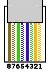
EIA/TIA 568 B – Straight Through |
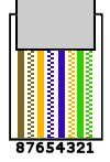
EIA/TIA 568 A –
|
 |
 |
Hold the grouped (and sorted) wires together tightly, between the thumb, and the forefinger. Get the wires lined up and nice and straight. Cut all of the wires at a perfect 90 degree angle from the cable at 12.5mm from the end of the cable jacket. This is a very critical step. If the wires are not cut straight, they may not all make contact.
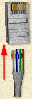
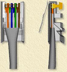
Push the wires the remaining way into the connector. Make sure that the wires have gone all the way in and are touching the end of the connector. You should see a line of 8 bare wire ends. If one is missing and that individual wire hasn’t gone far enough into the connector, pull the wires out, line up the ends and put them in again. You can’t see this problem from the side – you can only see it from the end. Now push the jacket as far as it will go into the connector. Be sure that the cable jacket goes into the back of the connector by about 3/16″.
Leads Direct makes great efforts to provide accurate and complete information. However, portions of the information contained in this website and any documents viewed on it or downloaded from it may be incorrect or not current. Any errors or omissions should be reported for investigation and correction. The information provided in any documents whether on our website or otherwise is provided "as is." No warranty of any kind, implied, expressed, or statutory, including but not limited to the warranties of non-infringement of third party rights, title, merchantability, fitness for a particular purpose, and freedom from computer virus, is given.