
Call Us Now:
0345 193 0615
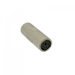
The standard PS/2 keyboard and mouse use a standard 6-pin mini-din connector to provide the interconnection between product and computer. The pins are set out as shown below:
|
6-Pin Mini-Din Female |
6-Pin Mini-Din Male |
| |
|
|
Viewed from the solder side of the connector |
|
In both cases, the pins normally have the following designations and functions:
| Pin | Name | Description |
| 1 | DATA | Key Data |
| 2 | n/c | Not connected |
|
3 |
GND | Ground |
| 4 | VCC | Power , +5 VDC |
| 5 | CLK | Clock |
| 6 | n/c | Not connected |
The following table clarifies the function of the pin connections described above:
| Name | Function |
| Data | Mouse data packets or keyboard scan codes are sent serially from the mouse or keyboard to the computer on this single wire |
| Clock | This signal is sent from the mouse or keyboard to synchronise the data signal |
| VCC | This is a simple 5 volts signal for giving power to the mouse or keyboard |
| Ground | This is a common ground signal used as a return path for data and is a reference to logical 0 |
The PC keyboard implements a bi-directional protocol. The keyboard sends streams of data to the host, and the host can send data to the keyboard. These streams are known as scan codes, and are unique for each button on the keyboard: one stream is sent when the button is pressed; another when the button is released.
The keyboard is free to send data to the host when both the KBD Data and KBD Clock lines are high (Idle). The KBD Clock line can be used as a ‘Clear to Send’ line. If the host takes the KBD Clock line low, the keyboard will buffer any data until the KBD Clock is released (i.e. goes high). Should the host take the KBD Data line low, then the keyboard will prepare to accept a command from the host.
The transmission of data in the forward direction (i.e. keyboard to host) is done with a frame of 11 bits. The first bit is a Start Bit (Logic 0) followed by 8 data bits (LSB First), one Parity Bit (Odd Parity) and a Stop Bit (Logic 1). The keyboard will generate the clock (typical frequency of the clock signal ranges from 20 to 30 Khz).
When the PS/2 mouse sends information, it must send 3 consecutive data packets in a row. Each packet sent has different information representing the button pressed (if applicable), plus the amount and direction of movement.
Each clock period for the mouse is usually between 70 and 150 microseconds (10 to 25 microseconds for transitions and 30 to 50 microseconds for high or low state). These may seem to be large margins but it works well, as this is a synchronous port – and also because it reduces the implementation costs (using high-precision clocks would vastly increase the cost of keyboards and mice, as well as computers).
The data line transition is made on the falling edge of the clock signal, and is usually sampled when the clock is low. Each data packet is composed of 11 bits, 1 start bit (which is low), 8 data bits, 1 odd parity bit and 1 stop bit (high).
Leads Direct makes great efforts to provide accurate and complete information. However, portions of the information contained in this website and any documents viewed on it or downloaded from it may be incorrect or not current. Any errors or omissions should be reported for investigation and correction. The information provided in any documents whether on our website or otherwise is provided "as is." No warranty of any kind, implied, expressed, or statutory, including but not limited to the warranties of non-infringement of third party rights, title, merchantability, fitness for a particular purpose, and freedom from computer virus, is given.