
Call Us Now:
0345 193 0615
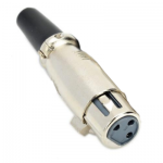
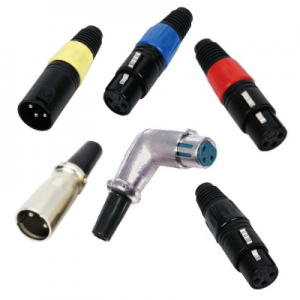 The XLR connector is used for various audio purposes including microphones, loudspeakers, and even lighting.
The connector is often known as a cannon plug or cannon connector in reference to its original manufacturer, James H. Cannon who was the founder of Cannon Electric in Los Angeles, California. The connector was originally called the “Cannon X” series, subsequent versions added a Latch (“Cannon XL”) and then a Rubber compound surrounding the contacts, which led to the abbreviation XLR. Many companies now make XLR connectors the most notable being Neutrik and Switchcraft.
The initials “XLR” have nothing to do with the pinout of the connector. XLR connectors can have other numbers of pins besides three – models with 4, 5, 6, and 7 pins have been made, but 3 and 5 pin models are the most common. Mini XLR connectors are also available with 3, 4 or 5 pins.
XLR connectors are superficially similar to the older, smaller, and less rugged DIN connector range, but are not physically compatible with them.
Originally developed by Cannon (now ITT Cannon) the connector was derived from some of its older predecessors, the O, P, UA and X connectors from the Cannon range.
The X connector was similar to the current connector but it had no latch. Cannon rearranged the pins and added a latch, and the XL (X series with Latch) was born. One of the great features of this connector is that the female pin 1 contact was placed forward in the shell and thus made connection first and broke connection last. Since pin 1 was used for the cable shield this greatly reduced the chance for hum or buzz as connectors were plugged and unplugged. This is the connector others such as Switchcraft and later Neutrik have copied.
Later Cannon modified the female end only to put the contacts in a Resilient polychloroprene compound. They called this new version the XLR series. No other company has copied this feature. It is amusing that XLR has become the generic term since what everyone else copied was the XL and not the XLR! The XLR line also was the first to introduce smaller rectangular flanges on the panel mounting versions of the connector. This allowed a higher density of connectors on a panel.
The IEC standardised the dimensions of the XLR type connector but specified a very loose tolerance for the distance from the end of the female contact carrier to the body of the connector. Switchcraft brand connectors (and copies of them from Asia) are made to the shorter end of the allowed tolerance range, while Neutrik brand connectors (and copies of them from Asia) are made towards the long end of the allowed tolerance range. At times this results in connectors that will not latch when manufacturers don’t properly follow the IEC Standard for their male connectors.
The PIN numbers are usually identified on the connectors. To determine which is which from the connection or solder side, hold the item with the two pins at the top and the single pin at the bottom:
The female XLR connectors are designed to first connect pin 1 (the earth pin), before the other pins make contact, when a male XLR connector is inserted. With the ground connection established before the signal lines are connected, the insertion (and removal) of XLR connectors in live equipment is possible without picking up external signals (as it usually happens with, for example, RCA connectors).
An unbalanced microphone can only be used up to a maximum of 10 meters away from the amplifier. Any more than this and noise problems become apparent. A balanced microphone will allow cable runs of up to 100m without any loss of performance. .For unbalanced operation, a single core screened microphone cable can be used, but for a balanced line a twin core screened cable is required.
BALANCED operation
UNBALANCED operation
An easy way to remember how they should be wired for balanced Audio is:
XLR speaker connections only use two of the three pins, and it is critical not to get speaker and microphone cables confused when setting up equipment. If you use a speaker XLR cable for microphone you will get a lot of rather nasty noise. If you use a microphone cable for connecting a speaker it will work for some time but the sound will get worse and worse over time and the cable will be damaged by the higher voltage and will not work properly if used with a microphone at a later date. The wiring for this type of connection is:
|
Pin |
Signal |
Description |
|
1 |
Negative | Negative Signal |
|
2 |
Positive | Positive signal |
|
3 |
Not connected |
DMX cables are most commonly made with 2 core shielded data cable terminated at either end with 3 or 5 pin XLR connectors (one male, one female). The DMX data itself requires only 2 of the cable cores plus the shield so recent devices have moved to the 3 pin format. However some older units still use the 5 pin connectors with only three pins used.
|
Pin |
Signal |
Description |
|
1 |
Signal Common | Earth / Ground / Shield |
|
2 |
Data Minus | Negative signal |
|
3 |
Data Plus | Positive signal |
|
Pin |
Signal |
Description |
|
1 |
Signal Common | Earth / Ground / Shield |
|
2 |
Data Minus | Negative signal |
|
3 |
Data Plus | Positive signal |
|
4 |
Not used | originally intended for feeding diagnostic data back to the DMX512 controller, but never implemented. Sometimes used to carry other data or power |
|
5 |
Not used |
Leads Direct makes great efforts to provide accurate and complete information. However, portions of the information contained in this website and any documents viewed on it or downloaded from it may be incorrect or not current. Any errors or omissions should be reported for investigation and correction. The information provided in any documents whether on our website or otherwise is provided "as is." No warranty of any kind, implied, expressed, or statutory, including but not limited to the warranties of non-infringement of third party rights, title, merchantability, fitness for a particular purpose, and freedom from computer virus, is given.